
Crossbolt
Elite Cafe Member
I had an idea the other day that yielded some results and I thought I’d pass this on in case it inspires anyone else who might find the approach useful.
I’m one of those folks who definitely needs to draw before cutting. However, as we all know, transferring two dimensional information to a three dimensional object has some drawbacks. Map distortions come to my mind most readily. When it comes to drawing for gun engraving I find it very difficult to assess how designs will transfer to the curved surfaces on a shotgun from a two dimensional drawing. I find the fences (balls to Americans) of side by side shotguns are particularly challenging in this regard. As luck would have it that is the engraving I am most interested in.
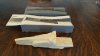
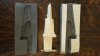
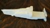
I recently had an idea on how to overcome this problem without doing repeated layout and rework on a subject gun based which, among others things, exposes the gun to potential damage. Repeated layout on the real thing doesn’t allow for easy experimentation either. My solution was to create a 3d model to work on. The way I went about doing this was to form an initial model out of artist’s plasticine based on measurements from a typical sidelock. I then used this master to create a “rubber†mold which I could use to make a resin cast. In the photograph the cast looks a little rough but after removing flash and sanding I found the cast a reasonably close facsimile of the sidelock. I’ve run a test on it and the hardened, sanded resin takes pencil and pen reasonably well including easy erasing of the pencil and, with light sanding, removal of pen marks.
The first time I used this, it allowed me in rather quickly and effectively (a couple hours) to solve design layout issues I was having based on paper studies. In fact, it worked so well for me I’m going to make a boxlock version for another project I have in mind. A side benefit of this is that with the mold made I can now make multiple casts, draw on them and put them aside as a record of variants to compare for effectiveness in layout design. I’ve not done it but I suppose colored pens and paint would even allow for mockup of final appearance of blacked, inlaid and other features.
I’ll post under a different thread an actual marked up example so folks can see what an inked up example looks like.
Jeremy
I’m one of those folks who definitely needs to draw before cutting. However, as we all know, transferring two dimensional information to a three dimensional object has some drawbacks. Map distortions come to my mind most readily. When it comes to drawing for gun engraving I find it very difficult to assess how designs will transfer to the curved surfaces on a shotgun from a two dimensional drawing. I find the fences (balls to Americans) of side by side shotguns are particularly challenging in this regard. As luck would have it that is the engraving I am most interested in.
I recently had an idea on how to overcome this problem without doing repeated layout and rework on a subject gun based which, among others things, exposes the gun to potential damage. Repeated layout on the real thing doesn’t allow for easy experimentation either. My solution was to create a 3d model to work on. The way I went about doing this was to form an initial model out of artist’s plasticine based on measurements from a typical sidelock. I then used this master to create a “rubber†mold which I could use to make a resin cast. In the photograph the cast looks a little rough but after removing flash and sanding I found the cast a reasonably close facsimile of the sidelock. I’ve run a test on it and the hardened, sanded resin takes pencil and pen reasonably well including easy erasing of the pencil and, with light sanding, removal of pen marks.
The first time I used this, it allowed me in rather quickly and effectively (a couple hours) to solve design layout issues I was having based on paper studies. In fact, it worked so well for me I’m going to make a boxlock version for another project I have in mind. A side benefit of this is that with the mold made I can now make multiple casts, draw on them and put them aside as a record of variants to compare for effectiveness in layout design. I’ve not done it but I suppose colored pens and paint would even allow for mockup of final appearance of blacked, inlaid and other features.
I’ll post under a different thread an actual marked up example so folks can see what an inked up example looks like.
Jeremy
Attachments
-
 cast 3.jpg70.3 KB · Views: 140
 -
 cast 2.jpg68.3 KB · Views: 139
 -
 cast.jpg67.4 KB · Views: 139


